CAD-friendly visualization#
A generic mesh viewer renders the triangulation. Turn edges on
(show_edges=True) and you see every facet boundary, an artifact of
the tessellation tolerance rather than a feature of the model. A CAD
application shows smoothly shaded faces with the model’s topological
edges (the B-rep feature curves) drawn on top.
pyvista-cad reproduces that pipeline.
How a CAD viewer renders#
A CAD kernel stores exact B-rep geometry: analytic / NURBS surfaces, trimmed faces, parametric edge curves. A GPU only draws triangles, so the viewer tessellates on load:
Each topological face is meshed independently to a tolerance (linear + angular deflection).
Per-node analytic surface normals are kept, so a coarse mesh still shades smooth (a 12-facet cylinder looks round).
Each topological edge is turned into a polyline and drawn over the shaded faces with a depth bias so it never z-fights the surface.
The triangle-mesh edges are never shown; the topological edges are.
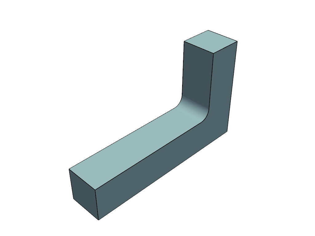
One-shot plot#
The .cad accessor adds a CAD-friendly plot() alongside the usual
mesh.plot(). The render below is live; drag to orbit:
import pyvista_cad
from pyvista_cad import examples

mb = pyvista_cad.read_step(examples.bracket_step_path())
mb.cad.plot()          # shaded faces + B-rep edges
Compare the generic triangle view (mesh edges are tessellation noise):
import pyvista_cad
from pyvista_cad import examples

mb = pyvista_cad.read_step(examples.bracket_step_path())
mb.combine().plot(show_edges=True)

plot() recovers the originating B-rep cached by the readers. For a
plain mesh with no B-rep origin it falls back to crease feature-edge
extraction (an approximation, since there is no topology to recover).
The plotter component#
For scripted scenes, use the cad plotter component:
import pyvista as pv
import pyvista_cad

pl = pv.Plotter()
pl.cad.add(mb, line_width=3.0)
pl.cad.add(other, silhouette=True)   # outline-only, for drawings
pl.show()
add() accepts a MultiBlock, PolyData, raw TopoDS, or a
build123d / cadquery object. Key keywords: edges (overlay on/off),
edge_color (defaults to the theme edge colour), line_width,
render_lines_as_tubes, silhouette, smooth.
The data behind the render#
cad_view() returns the same resolution as data, useful for
inspection, picking, or per-face styling:
cad = mb.cad.cad_view(linear_deflection=0.2)

faces = cad['faces']   # per-face MultiBlock, each block carries
                        # cad.face_id and analytic point Normals
edges = cad['edges']   # polylines; cell arrays cad.edge_id and
                        # cad.edge_kind (0=line, 1=circle, 2=ellipse,
                        # 6=bspline, ...; see cad.edge_kind_legend)
The free functions pyvista_cad.topods_to_edges,
topods_to_multiblock, flatten_to_cad_polydata, and
as_cad_multiblock expose the same machinery for raw OCCT shapes.
The dual .cad accessor#
.cad is registered on both pv.DataSet and pv.MultiBlock. On a
dataset it resolves to CadDataSetAccessor; on a MultiBlock to
CadMultiBlockAccessor. PyVista picks the class by object type, so the
same .cad.plot() / .cad.cad_view() / .cad.tessellate() calls work
on a single part and on an assembly. The MultiBlock accessor adds
assembly-tree traversal: walk(), find(), assembly_tree(),
flatten(), and flatten_to_polydata().
Metadata#
The readers stamp cad.* field data that survives downstream PyVista
filters. The accessor surfaces it as read-only properties: units,
label, color (RGB or RGBA in [0, 1]; alpha rides on the color,
there is no separate opacity key), plus source_format,
source_format_version, and the live metadata view
(CadMetadata). Write the standard keys back with
set_metadata(units=..., label=..., color=..., transform=..., source_format=..., source_format_version=..., guid=..., metadata=...);
it validates each value and replaces (not merges) the stored cad.*
schema. set_units(target, convert=True) additionally rescales point
coordinates by the unit ratio.
tessellate() refines the mesh from the cached originating B-rep; it
raises TessellationError on a mesh with no
CAD/B-rep origin (there is no analytic geometry to re-mesh). The same
applies to exact_volume() / center_of_mass(), which raise
CadError without a cached TopoDS_Shape.
Writing#
read/write cover STEP, BREP, DXF, and 3MF (round-trip); IGES, SCAD,
and FCStd are read-only; glTF is read and write. Writing a
pv.MultiBlock to STEP via write_step (or .cad.to_step()) emits a
labelled OCAF assembly by default (write_assembly=True), one
component per block with its block name as the part label; pass
write_assembly=False for a single fused solid.
Notes#
Edge polylines are recovered from the face triangulation (
PolygonOnTriangulation), so they lie exactly on the rendered facets at zero extra meshing cost. Edges shared by two faces carry duplicate coincident points; harmless for line rendering.Face-less wireframe edges (e.g. IGES construction curves) fall back to direct 3D curve sampling.
Analytic normals come from the OCCT triangulation when present, otherwise from evaluating the underlying
Geom_Surfaceat each node’s UV.